Overture: An Introduction to ConSerts
Conditional Safety Certificates (ConSerts) offer a novel way to assure the safety of open and adaptive systems. They work in a model-based manner, leveraging type systems, boolean success trees, and demand-guarantee logic to formalize safety concepts.
This book is an introduction to the concept of ConSerts, showing their use cases, integration in the overall systems safety process, as well as details on the implementation (both during design- and runtime). The book is targeted towards practitioners and aims to provide a go-to-reference for learning more about ConSerts, an approach that has so far been primarily accessible in the form of scientific publications.
This book is authored by Fraunhofer IESE, but intended to be open-source so that other authors can contribute their experiences, use cases, or additions with respect to ConSerts. More legal details can be found here.

Safety Engineering Lifecycle with ConSerts
Collaborative systems undergo the process from envisioning the system at design time, developing it, down to the operation. These three phases in the product and service lifecycle are outlined in the following diagram. We put a particular focus on the safety engineering of the system. On the left, different roles are depicted.
According to established safety standards (such as the ISO61508), only the grey boxes are present: The safety analysis is executed as mandated by relevant standards for the domain. First, the system is defined in terms of use case and product requirements. Afterwards, a preliminary hazard and risk analysis (HARA) is executed, which helps to find safety goals. The assurance of these safety goals is developed in an assurance case, using goal structuring notation. This analysis informs product development and eventually, the operating time is impacted either through technical or organizational measures.

With Conditional Safety Certificates (ConSerts), this approach is altered:
-
In addition to the traditional components of the system definition, a Domain Engineering Process is executed (1), defining the important terms and concepts of the domain in a type system. We envision this to be done by standardization organizations or comparable institutions. Existing efforts where this can be added are the IEC 61360 Common Data Dictionary.
-
At the bottom of the V-process, we Derive ConSerts (2) which are model-based arguments that our system is safe, given the conditions stated in terms of the type system are satisfied. This derivation is done on the basis of the assurance case, which directly shows properties to be assured at runtime and/or collaborating partners to be present. Verification and Validation activities are executed as well.
-
The ConSert is then exported (3) as a Digital Dependability Identity (DDI) compliant with the Open Dependability Exchange (ODE) format to make it usable further down the process.
-
During development time, the ConSert is integrated into the existing process to create a product. Here, we show an example from the Industry 4.0 domain. The ConSert is used to generate a ConSert-Monitor (used at evaluation time) and a ConSert Submodel (used at composition time). Both are packaged into Asset Administration Shells (AAS) that can be exchanged with the AASX format (4).
-
At runtime, e.g. in the factory, these artefacts are used to implement the safety concepts. When collaborating systems are grouped together and reconfigured, the ConSerts of all the individual systems are composed (5) to check if they are compatible and can, in principle, be operated safely. If this is the case, the ConSert monitors are deployed. These monitors collect the runtime evidence local to the system as well as guarantees from other systems (6). If their demands can be fulfilled and runtime evidence are given, the system might itself be able to give further guarantees to other systems.
In summary, the ConSert-based methodology allows us to move from a model-based safety engineering design process to model-based safety assurance at runtime in the factory. This way, the link between high-level safety goals and low-level checks at runtime is maintained and can, in the spirit of continuous safety assurance, be updated when necessary.
ConSerts Lifecycle
There are different times in the lifecycle of a ConSert.
A ConSert is created at Design & Development Time and used at Runtime.
At runtime we also have to distinguish between two times:
-
Composition time: When we check whether the ConSerts of constituent systems are conceptually compatible (e.g. for a reconfiguration of our system).
-
Evaluation time: When we check whether the ConSerts of constituted systems can currently cooperate.
So to summarize in one sentence: Typically, a ConSert spends most of its time in the evaluation time, occasionally it is in composition time and before it is put into use, it is in design/development time.
Graphically, this looks like this:

Tools that help
At design time, safeTbox supports the development of ConSerts that result in exported model files.
At development time and runtime, conserts-rs is used for:
-
Composition: With
conserts compose ...multiple ConSerts model files can be checked for compatibility. Being a CLI utility, the output can be consumed via exit codes (allow composition or not) or verbosely, in order to report it to a user. -
Evaluation: With
conserts compilea ConSert model file can be compiled to a Rust crate. This is used at development time when the constituent system is built. Hence, at runtime the structure cannot change, but the output changes depending on the inputs.
Design & Development Time
The first phase in the lifecycle of a ConSert is the design and development time. At this stage, safety engineers consider the planned system, its requirements, as well as impacts of these on safety.
ConSerts are a runtime means to implement specific parts of an assurance case (AC) — those that are affected by dynamic changes in the system and environment.
In model-based safety engineering, an AC contains a set of evidence (in AC terms: Solutions) at the leaf level, which proves that the argument can be given.
The approach of an AC is thereby similar to a success tree, where a top-level Goal is successfully fulfilled if sufficient leaf-level successes are there.
Here is an examplary, incomplete AC showing the different elements of it:

Assurance Case Development
Starting from a hazard- and risk analysis for a given nominal function, assurance cases are built up. Note that there will not be a single assurance case, but a set of these — one per collaborating system.
The top-level assurance case has a top-level goal of "safe nominal function". From this, an argumentation strategy is devised. At some location, the argumentation strategy will encounter a solution of the form "if another system provides a service with the following properties". These are the "intended breaking points" in between the collaborative systems. Hence, the current assurance case ends at this location and another assurance case is built up for the "other system".
Top-Level Application

Lower Level System

Assurance Case to ConSert
Based on the set of Assurance Cases we developed before, we can derive the ConSerts as follows:
- For each assurance case, we consider the top-level goals as a
ProvidedService(withGuarantee) and leaf-level solutions that start with "if another system" as ConSertRequiredService(withDemands). In this step, the semi-formal description can be formalized using dimensions. - Other leaf-level solutions can be turned into
RuntimeEvidence, if they can only be given at runtime. Again, dimensions are used as appropriate. This runtime evidence can be sensor measurements (to be checked automatically) or manual checks or assumptions about the environment (e.g. the workspace is built in accordance with a certain norm). - Eventually, the AC is analyzed and its logic (e.g. "argument over all ..." / "argument over at least one ...") are then translated into
Gates of the ConSert trees (e.g. And / Or). In this process, each guarantee gets its own ConSert tree that specifies which evidence is required for it to become valid.
Note that it can well be that an argument might be turned into multiple instances in the ConSert, e.g. because properties of demands have a direct relationship to their guarantees. In the worked example, the assurance case captures how multiple robot speed guarantees and matching demands can be generated that follow the same argumentation pattern (only being different in the accepted value ranges they provide/require).
Composition Time
When ConSerts have been created and stored together with the systems they certify, we enter the runtime. At runtime, we have emergent collaborations between multiple systems that each carry their ConSert. In this scenario, the composition is used to assess the safety of the collaboration.
To achieve this, the collaborating ConSerts are put into a directed acyclic systems graph. For this graph, the following rules apply:
- First, ConSerts without demands become leaf-nodes of the systems' tree.
- ConSerts with demands become additional nodes of the tree. For each them, the following applies:
- We consider all demands of the ConSert and search for other nodes in the systems' tree with matching guarantees.
- For each matching node, we insert a directed edge from the node satisfying the demand to the node with the demand.
- If the node we are about to insert has at least one demand that cannot be fulfilled at all, we fail to insert it.
- Integrating ConSerts with demands can fail if done in the wrong order (i.e. the ConSert with the matching guarantee might not have been inserted yet). Due to the complexity of this approach, the order is left to the user and not figured out automatically.
Composition checks are done as follows:
- Guarantee and Demand must have the identical functional service type.
- The dimensions of both must be compatible:
- For the dimension of the demand, there must be the matching dimension in the guarantee.
- Only if both dimensions are binary, categorical, or numerical, they could be matching.
- If they are categorical, the guarantee's possible values should at least be those required by the demand to be a match (or the other way round, depending on the dimensions subset relationship).
- If they are numerical, the guarantee's range should at least include the range of the demand to be a match (or the other way round, see above).
Evaluation Time
As soon as we have composed a set of systems successfully using their ConSerts, they also collaborate in exchanging live information about their safety. Each system is equipped with a ConSert-Runtime monitor (generated via conserts-rs), whose task is to:
- collect runtime evidence, both locally from the system (
RuntimeEvidence) as well as receive it from other systems (Guarantees of other the system, fulfilling the localDemand). - keep a statistical filter with a certain window on the runtime evidence and use majority voted evidence to compute which
Guarantees this system can give. - send out which guarantees can be given at this point in time.
Analysis Pipeline
#![allow(unused)]
fn main() {
// collect runtime properties
let runtime_properties = RuntimeProperties {
    ...
}; // boolean and numerical properties

// update runtime_properties, often concurrently
monitor.add_sample(runtime_properties);

let runtime_evidence = monitor.get_sample(); // boolean evaluations, majority-filtered

// evaluate safety guarantees
let guarantee1 = Guarantee1::evaluate(&runtime_evidence);
}
Performance Benchmark
As this step is executed all the time during operation, safety inference is the most performance-critical task and it must be ensured that it does not impede the nominal function of the system. As we often target embedded, resource-constrained systems, both computation time and code size are imporant metrics.
The following shows how the size (in terms of number of runtime evidence) has an impact on both quantities of the generated ConSert Runtime monitor.
Inference Time

Here, two times have been measured (and linear regression was applied to plot the lines). The following snippet shows where the timestamps have been taken:
#![allow(unused)]
fn main() {
#[task(resources = [safe, monitor, rtp])]
fn evaluate_safety(cx: evaluate_safety::Context) {
    let start = Instant::now();
    let resources = cx.resources;
    // Move current sample to monitor
    resources.monitor.add_sample(*resources.rtp);
    *resources.rtp = RuntimeProperties::unknown();

    // Evaluate safety
    let rte = resources.monitor.get_sample();
    let cycle_time = start.elapsed().as_cycles();
    *resources.safe = guarantees::Guarantee1::evaluate(&rte);
    let eval_time = start.elapsed().as_cycles();
    // 64MHz -> 1 cycle = 16 ns = 0.016 us
    defmt::info!(
        "CYCL {:?} EVAL {:?} cycles",
        cycle_time,
        eval_time - cycle_time
    );
}
}
Binary Size

Evaluation Details
We employed a Nordic Semiconductor board (nRF52840), with a 64MHz ARM Cortex-M4 core with FPU, 1MB Flash, and 256 kB RAM.
While this board is not used in the safety-critical domain, the hardware resources are comparable with chips used in that domain with respect to processor speed and available memory.
All Rust code was compiled using the --release flag and no additional Cargo options.
The monitor has been generated with a statistical filter depth of 3 for all of the used runtime evidence. The evidence has all been set to false and was aggregated via an OR gate, leading to worst-case performance as all logic operations must be executed.
Verification and Validation
The preceding sections have dealt with the left side of the V-model and did not mention verfication and validation (V&V) activities in detail. This is the purpose of this section to show how we can V&V ConSerts.
When it comes to the engineering of ConSerts, we have several layers (top-to-bottom as in the V-model):
- ConSert Model Contents
- ConSert Model Transformation
- ConSert Runtime Monitor
ConSert Model Contents
At the highest level, we deal with the ConSert model that formalizes the service-oriented safety relations between multiple systems. In this step, we have to verify that the ConSert has the right elements, given a safety assessment of the collaborative systems.
ConSert Model Transformation
At the middle level, the ConSert model is turned into Rust code elements, i.e. guarantees and their evaluation trees are rendered into structs as well as fn evaluate(g: Guarantee) -> bool.
To validate this, a test kit for potential users can be used to prove equivalence of input models and output code.
Further, manual code review can be performed, as the code complexity can be handled well.
Our measurements yielded that in addition to static 150 lines of code (LoC) for the infrastructure, we have around 10 lines of code per element in the ConSert.
In total, this keeps the code to be reviewed to a tractable size.
ConSert Runtime Monitor
Finally, we have to verify that the runtime monitor is correct and correctly transformed into an executable binary. Again, code review allows to check for the correct generation of the monitor code.
Currently, the following steps (i.e. compilation) cannot yet be validated. However, there is a long term effort to create Ferrocene, a verified Rust compiler. Furthermore, it is intended to verify third-party Rust crates, such as heapless. In summary, these activities would enable the verification of the binary, proving that a runtime monitor is generated that is faithful to the original ConSert model.
Digital Dependability Identity
Within the Dependability Engineering Innovation for Cyber Physical Systems (DEIS) project, the concept of the Digital Dependability Identity (DDI) has been developed.
DDIs are formalized using the Open Dependability Exchange (ODE) metamodel, specified in EMF’s Ecore metamodel (an XML Metadata Interchange (XMI) specialization) and exported to well-established formats (e.g. XML). The major idea is to create tool-interoperability as depicted in this diagram:

The ODE layer incorporates information about the dependability of the system. At the techniques layer, we find different ways to analyze the different dependability properties of the system. Finally, the tools layer gives a collection of tools with different capabilities in terms of implemented techniques. The arrows indicate how transformations and tool-interactions can be achieved using the DDI concept.
ConSerts fit into this picture as another technique, in parallel to CFT or FMEA. So far, this has not yet been fully integrated.
ConSerts
The following shows an example ConSert:

A ConSert consists of:
- A set of Guarantees that can be provided at run-time, depending on the conditions.
- A set of Runtime Evidence which are gathered by the system itself.
- A set of Demands that the system has and which can be fulfilled by guarantees of other systems.
- Boolean success trees that combine runtime evidence and demands to find out whether a guarantee can be given or not. The tree supports the logic gates: And (&) and Or (||).
- Evidence as well as guarantees and demands can have a dimension.
Service Hierarchy
Not depicted here is that each guarantee belongs to one or more Provided Services. Analogously, each demand belongs to one or more Required Services. Each of these services have a type and only those with matching type can be combined. Systems (grey) and their services (green) build up a hierarchy like depicted in this diagram:

Note that there can be any number of layers and hence topologies of intermediate systems whose composition enables a high-level application service.
Preliminary DDI Content
Note: So far, ConSerts have not been completely integrated into the DDI framework. This is ongoing work in the SESAME project.
The following YAML is the machine-readable representation of the ConSert depicted above.
---
guarantees:
  - id: G_Distance
    description: Distance is kept
    dimension:
      Numeric:
        type: DistanceIsKept
        covered:
          - Inclusive:
              start: 0.0
              end: 5.0
        subset: Demand
        uom: millimeter
  - id: G_Approved
    description: Installation Approved
    dimension:
      Binary:
        type: InstallationApproved
evidence:
  - id: E_DistanceBound
    description: Distance <= 50m
    dimension:
      Numeric:
        type: Distance
        covered:
          - Inclusive:
              start: 0.0
              end: 50.0
        subset: Guarantee
        uom: meter
  - id: E_Approved
    description: HSE Approved Setup
    dimension:
      Binary:
        type: HSEApprovedSetup
demands:
  - id: Latency
    description: Transmission Latency <= 5ms
    dimension:
      Numeric:
        type: TransmissionLatency
        covered:
          - Inclusive:
              start: 0.0
              end: 5.0
        subset: Demand
        uom: millisecond
gates: []
tree_propagations:
  - from: E_DistanceBound
    to: G_Distance
  - from: E_Approved
    to: G_Distance
  - from: Latency
    to: G_Distance
  - from: E_Approved
    to: G_Approved
required_services:
  - id: LatencyService
    functional_service_type: Latency
    demands:
      - Latency
provided_services:
  - id: DistanceService
    functional_service_type: Distance
    guarantees:
      - G_Distance
Dimensions
In the context of collaborative cyber-physical systems, we are often faced with physical and digital quantities that must be measured, communicated, and acted upon. Hence, correct handling of these quantities must be ensured to avoid errors. In a ConSert, there are multiple elements that have a Dimension, in particular Guarantees, Demands, and Runtime Evidence. The ConSert software (both conserts-rs and the generated crate) leverages the uom crate to have type-safe zero-cost dimensional analysis.
Relevance of Dimensions for ConSerts
Dimensions are used for two use cases:
- At composition time, we check if demands are fulfilled by guarantees, i.e. the related subset relation (see below) is fulfilled.
- At evaluation time, the monitor code generated by conserts-rs exposes this information to make it clear to the developer what information is expected:
#![allow(unused)]
fn main() {
// Definition
#[doc = "Approximation Speed of Detected Object X m/s"]
#[derive(Clone, Copy, Debug, PartialEq)]
pub enum ApproximationSpeedOfDetectedObject {
    Unknown,
    Known(uom::si::f64::Velocity),
}

// Usage
let velocity : f64 = velocity_sensor.sample();
let rtp: RuntimeProperties = ...;
rtp.approximation_speed_of_detected_object =
    ApproximationSpeedOfDetectedObject::Known(
        Velocity::new::<meter_per_second>(velocity)
    );
}
Details of Dimensions
A dimension can be either
- binary (e.g., true, false), or
- categorial (e.g., good/medium/bad) or
- numerical (using a given number system).
In any case, a dimension has a unique type, derived from its name (e.g. ApproximationSpeedOfDetectedObject).
If we employ a numerical dimension, the dimension has a unit (e.g. "meter") or the unit is 1.
For demands and guarantees, a dimension has two properties:
- A
coveredset of values.- Intuitively speaking, this means which values are guaranteed (e.g. "I guarantee to be moving with at max. 2m/s" -> "0...2" is the covered set). The analogous applies for demands.
- Formally, this covered set of values can be expressed by a set of disjoint inclusive ranges.
- A
subsetrelationship of either:Demand, where the covered set of demand values must be subset to the covered set of guarantee values.Guarantee, where it is the other way round.
Graphically the subset relations look like this:
| Subset Relationship | Matching | Unmatched | Guide Sentence |
|---|---|---|---|
| \(G \subseteq D\) |  |  | Demand at most |
| \(D \subseteq G\) |  |  | Demand at least |
Dimensionless Elements
If an element does not have a specified dimension, a match is only made on the type of the element (e.g. a Guarantee InstallationApproved fulfills any demand InstallationApproved).
We could consider this as a binary, unit-less dimension, where true is covered and false is not.
A Worked Example
This section of Opus describes a use case of ConSerts in detail, showing the different stages in safety engineering, the use of various engineering artifacts, as well as concrete details on the safety assurance for the concrete use case. We use a robotic bin-picking scenario, where a human collaborates with the robot by providing or collecting boxes with material on the workbench.
The use case is provided by the KIT Intelligente Prozessautomation und Robotik (IAR-IPR) and has been developed as part of the FabOS project.
Before we get started, we have to answer the question why we are not using traditional industrial safety engineering (e.g. static risk analysis, static safety functions, and fixed configurations). With the continuous development towards bringing the Industry 4.0 idea to life, we see many applications that:
- require close collaboration between humans and robots (which don't allow complete physical separation)
- require regular changes in the setup (lot-size-one and other individualised production approaches)
With ConSerts, we are able to decouple components that form a concrete manufacturing system in an open and modular fashion.
This section is structured as follows:
-
System Description, showing the details of the use case.
-
Preliminary Hazard- and Risk-Analysis, where we apply traditional, norm-driven safety engineering to identify relevant safety goals.
-
Assurance Case with GSN, where we argue how the collaborating systems can conceptually be operated safely.
-
Conditional Safety Certificates that contain the safety information that must be assessed at runtime.
-
Runtime Artifacts that can be used at run-time to compose and evaluate safety-relevant information.
System Description

We use a robotic bin-picking scenario, where a human collaborates with the robot by providing or collecting boxes with material on the workbench. The robot is placed on the workbench that is also posing a limit on its working area. The major threat in this scenario is that the human might get injured, which is what we are going to avoid with the approaches presented in the following.
The diagram above depicts this:
- The grey bin boxes contain material that is processed by the robot.
- The light grey area is the workspace of the robot.
- Towards the north, the workspace is limited by a wall or fence.
Note that this scenario is intentionally generic, as the safety approaches developed are also generic. Hence, specific details such as the number of bins, the exact process steps executed by robot and human, are irrelevant.
Safety Analysis
Note: This is an exemplary document. The risk assessment is considering a real demonstrator system, but should not be considered complete and/or correct.
In order to assure the safety of the bin-picking use case, we execute a Safety Analysis, including Hazard And Risk Analysis (HARA), Safety Concept Derivation, and Verification.
First, we explore the regulatory landscape for the domain:

In the following we execute the HARA according to ISO12100. Here are some abbreviations:
- RI: Risk Index (1: Before Safety Measure, 2: After Safety Measure), computed according to risk graph in ISO TR 14121
- PL: Performance Level (concept from EN/ISO 13849-1 for technical measures)
- SIL: Safety Integrity Level (concept from IEC/EN 62061)
- C: Constructive Measure (inherently safe construction)
- T: Technical Measure
- CT: Control-Technical Measure
- U: User Information
Mechanical Hazards & Countermeasures
| Hazard | Consequence | Location / Lifecycle | RI (1) | Risk Reduction Measures | PL Required | PL Achieved | Residual Risk | RI (2) |
|---|---|---|---|---|---|---|---|---|
| Collision of Person w/ Robot Arm | Bruise, Fracture, Laceration | Commission, Operation | 4 | C: Lightweight Robot CT: Stepwise Speed Scaling | PL d | PL d | Fast Approach of Robot or malicious circumention can lead to collision | 1 |
| Pinch of body parts in between robot and obstacles | Bruise | Commission, Operation | 4 | CT: Four vertical safety layers constrain robot movement U: Correct installation | PL d | PL d | Inadequate deployment makes control-technical measure ineffective | 1 |
| Pinch of hand/arm between effector and table | Bruise | Commission, Operation | 2 | CT: Force of effector limited to 140N. Max. value for hands/fingers acc. to ISO/TS 15066 | PL d | PL d | - | - |
| Overthrowing tables | Bruise | Commission, Operation, Setup, Teardown | 1 | C: Connect tables with eath other to ensure safe stand | - | - | - | - |
| Pinch of fingers/hand due to grip of effector | Bruise | Commission, Operation | 2 | CT: Grip force limit to 100N | PL d | PL d | Low force bruise | 1 |
| Fall down of work material due to ineffectiv grip | Bruise | Commission, Operation | 2 | U: only use work material that is light enough to not cause injuries | - | - | - | - |
Here, we describe the safety measures in more detail:
- Stepwise Speed Scaling:
- Humans near the robot are detected via laser scanner.
- The speed of the robot is, at any time, scaled according to the current minimal distance between the human and the robot. Scaling is done in accordance with ISO/TS 15066, Sec. 5.5.4.
- If a minimal distance is no longer mainted, the robot executes a safe stop. The minimal distance is derived from ISO 13855, Sec. 6.3.
- Correct Installation:
- No obstacles should reach into the workspace of the robot.
- Minimal distances between safety layers and surrounding obstacles must be ensured, according to ISO 13854.
- Force Limitation:
- In this operation mode, it is required that for all possible collision scenarios, the resulting collision force and collision pressure are below certain body-part specific limits which are specified by ISO/TS 15066.
- Possible collision scenarios and affected body parts are determined in a risk assessment procedure before commissioning.
- Collision force limitation can be achieved by constructive measures (e.g. reduced robot mass, compliant joints), software measures (speed limitation, collision detection), or combinations of both.
- Compliance with the force limitation requirements can be validated through a calculation model or measurements.
Electrical Hazards & Countermeasures
| Hazard | Consequence | Location / Lifecycle | RI (1) | Risk Reduction Measures | PL/SIL | Residual Risk | RI (2) |
|---|---|---|---|---|---|---|---|
| Touching parts with present voltage | Electric Shock | Commission, Operation, Setup, Teardown | 5 | C: Avoid contact of parts with present voltage T: Robot Control Device U: Only briefed staff can open cabinet U: Warning on harmful voltage U: Visual inspection of isolation | - | Isolation could be damaged or warnings can be ignored | 2 |
Here, we describe the safety measures in more detail:
- Avoid Contact of Parts with Present Voltage:
- Robot and Robot Control Device: only use original components of vendor, no eletric modifications
- Laserscanner, Scanner Control Device: use low voltage (<= 24V), guard from touching through locked switch cabinet.
- Power Supply Gripper: use low voltage (<= 24V)
- Power Supply, Power Adapter: guard from touching through locked switch cabinet.
Other Hazards & Countermeasures
| Hazard | Consequence | Location / Lifecycle | RI (1) | Risk Reduction Measures | PL/SIL | Residual Risk | RI (2) |
|---|---|---|---|---|---|---|---|
| Bystanders could unintentionally / maliciously interfere with control | Various injuries | Operation | 5 | T: Areas not covered by scanner must be made inaccessible by other means U: Operators have to oversee operation | - | Unintentional / malicious activation of control | 2 |
| Emergency stop is not reachable in critical situation | Various injuires | Commission, Operation | 3 | U: During operations, emergency stop button must be within operator's reach | - | Emergency stop button cannot be reached in time (e.g. slow reaction). | 1 |
Assurance Case
The following sections show the Assurance Cases developed for the overall use case and application, as well as system-level Assurance Cases that are translated into ConSerts in the next step.
Human-Robot Collaboration Application
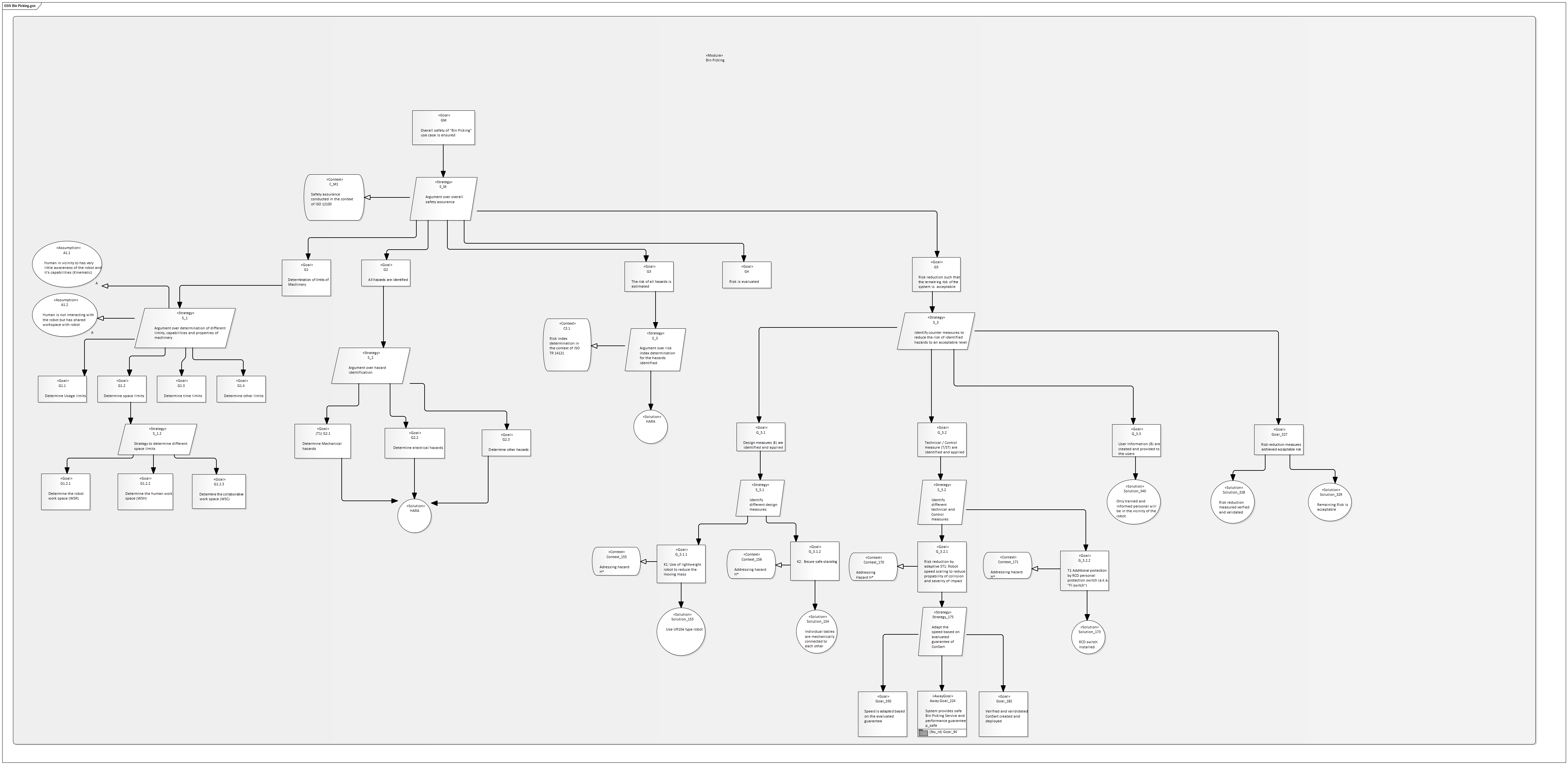
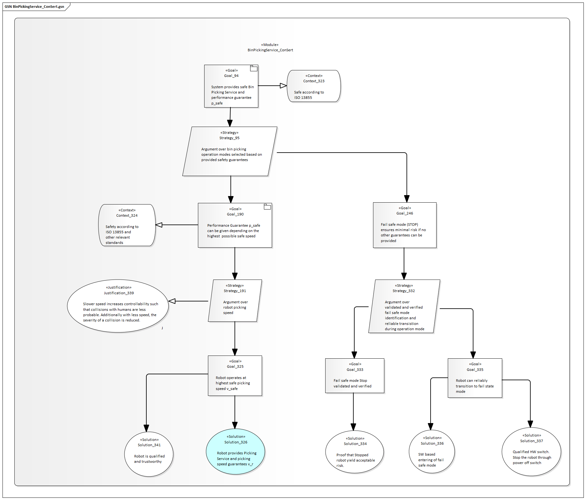
Bin Picking Service
Robot
Workspace
Scanner
Camera
ConSerts
At the system level, we have the following composition of services:

Bin-Picking Application
At the application service level, we have the bin-picking application:

Depending on the provided performance of the robot, the high-level service can be provided with a different performance. Concretely, a robot moving at full speed can process more items in the same time than if it runs at reduced speed. In this use case, this is a 1:1 mapping, but more complex scenarios could have more intricate interactions between the performance of collaborating systems and the overall service performance.
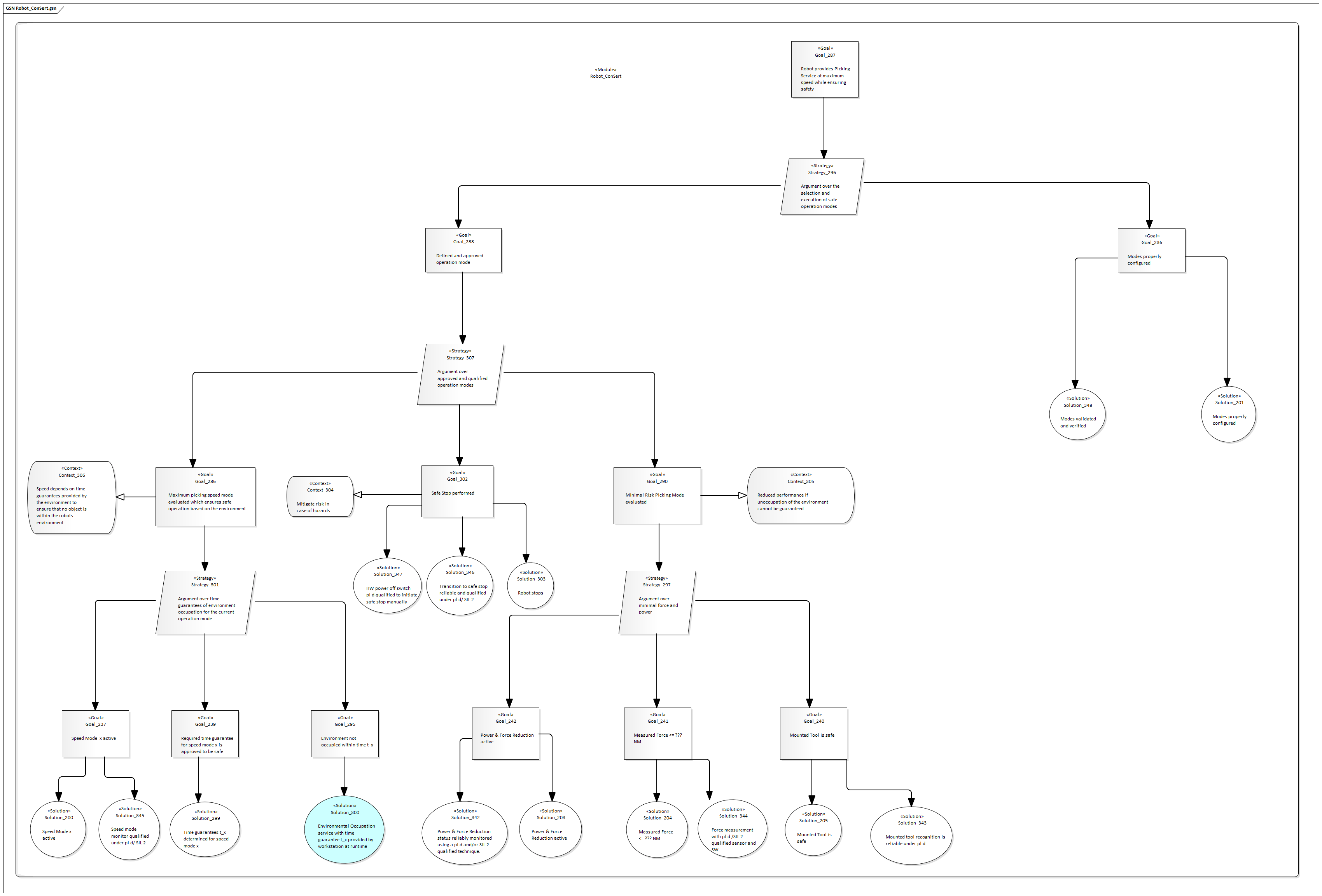
Robot
The high-level performance is primarily impacted by the robot arm:

The robot has demands in terms of an unoccupied environment. The major quantity that must be guaranteed is the worst-case time window the environment can be guaranteed to be free. The robot arm's current speed has a major impact on this requirement, as its stopping time is dependent on this. Obviously, the run-time evidence "Modes properly configured" is required and checked manually by the health and safety engineer.
For each configured speed mode, we find the appropriate time \(0 .. t\) by considering the following measures and their effect on the worst-case stopping distance:
- Robot Arm Speed: deccelerating to 0 takes longer for higher speeds.
- Robot Arm Elevation: the arm might be closer to the edge of the workspace.
- Robot Arm Load: higher load means higher inertia and longer time to stop.
- Electric Response Time: is spent between the detection of a signal and the stop action.
Using the worst-case human speed, we can turn this into a time value \(t\).
Note that the ConSert could be more detailed if the robot has more sensing capabilities:
- If the loads of the arm are known, multiple values for its impact on the stopping time can be provided. Hence, lightly loaded arms can move faster.
- If the elevation is known, multiple values for its impact can be provided.
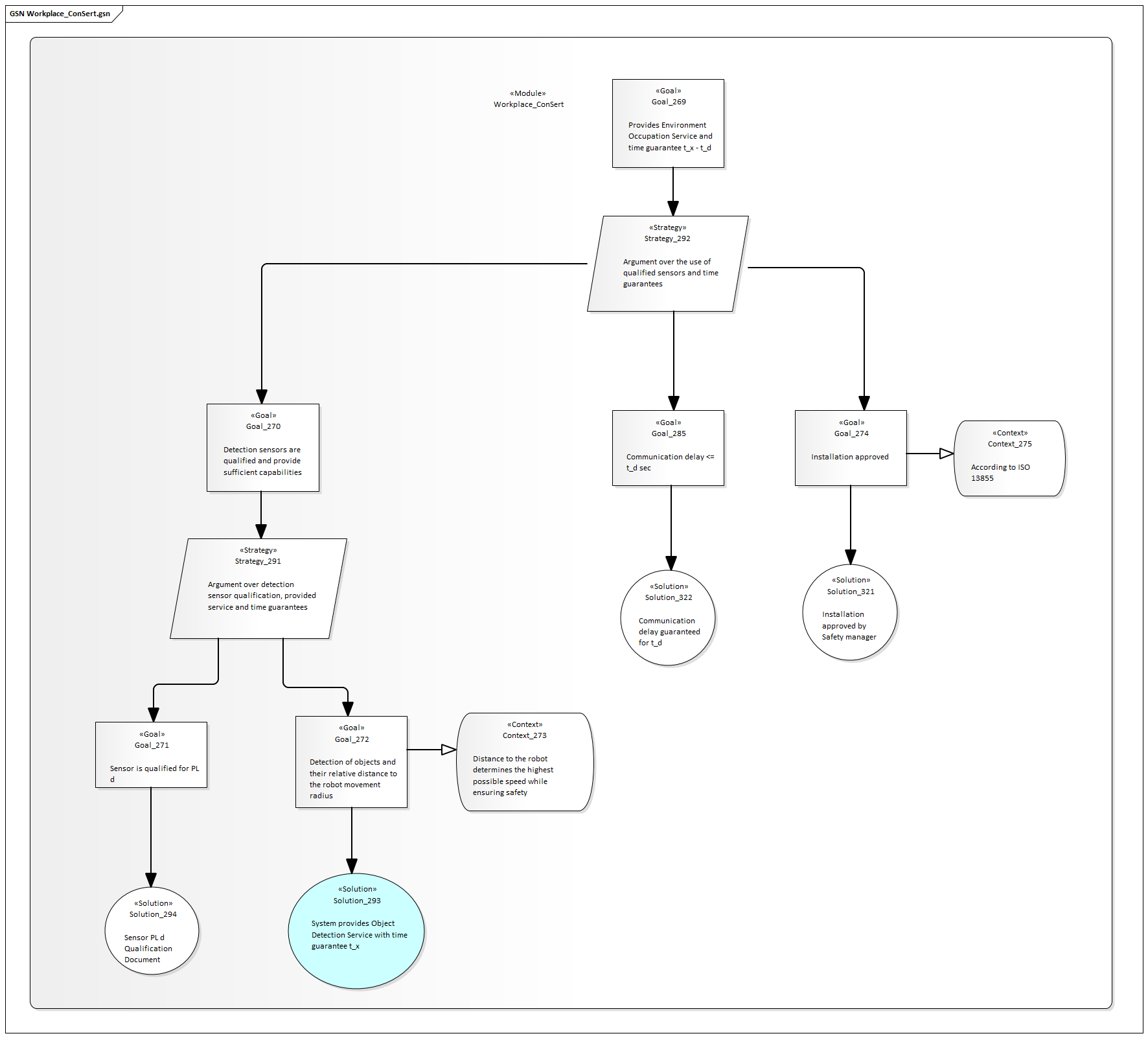
Workspace
Providing guarantees about an unoccupied environment is done by the workspace:

In the workspace, we rely on a) detection services (e.g. sensors) as well as b) static measures (e.g. walls, fences) to guarantee a minimal time that is required for a human to go through the workspace into the robot's operation area. We account for network communication delays (communicating the guarantees and demands between sensor and robot), reducing the guaranteed value appropriately, as well as other surcharges due to the setup of the workspace. We further require a manual run-time evidence "Installation approved by HSE".
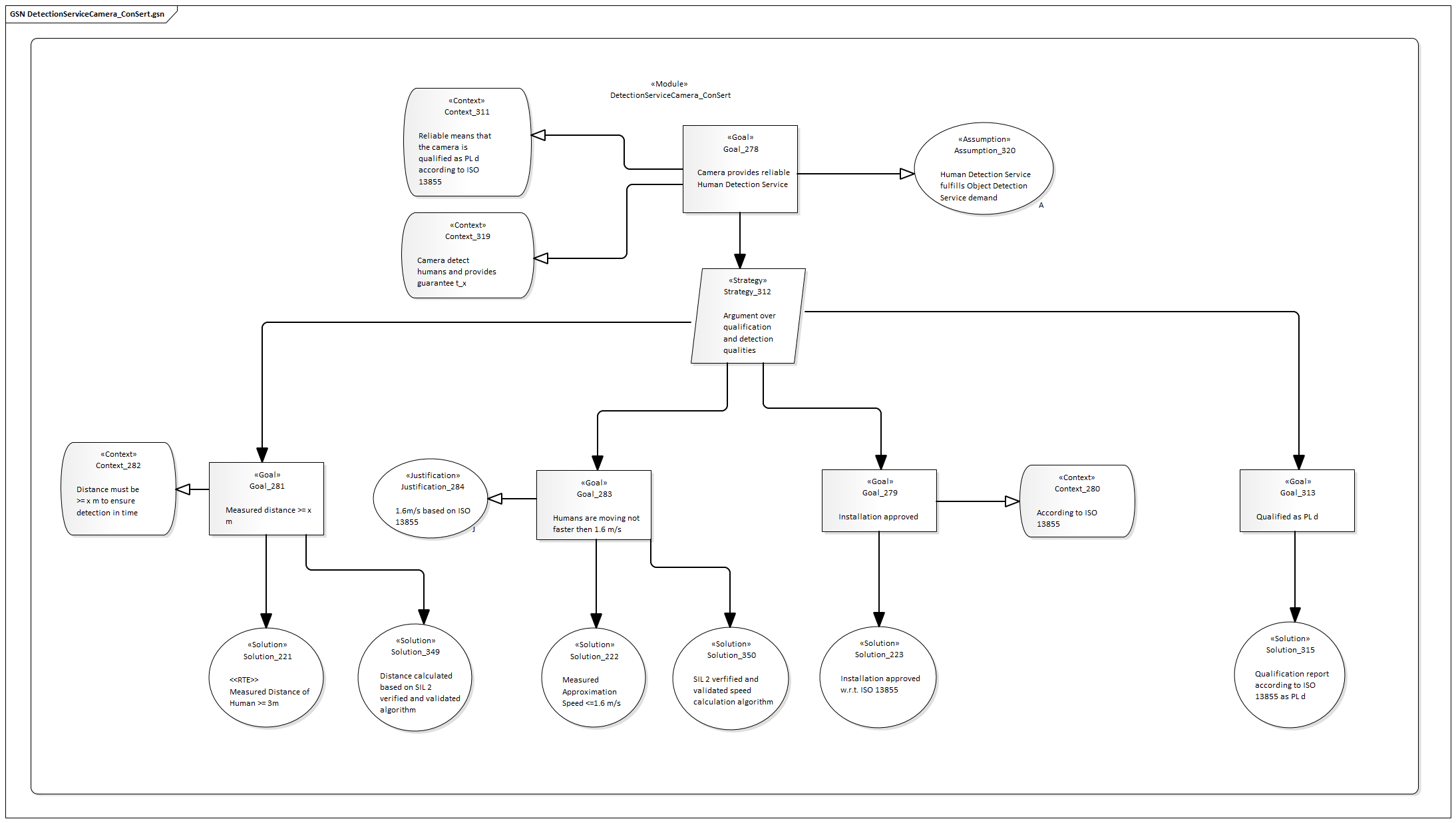
Environment Detectors
Eventually, the environment detectors provide us with run-time information about the unoccupied state of the area around the robot:
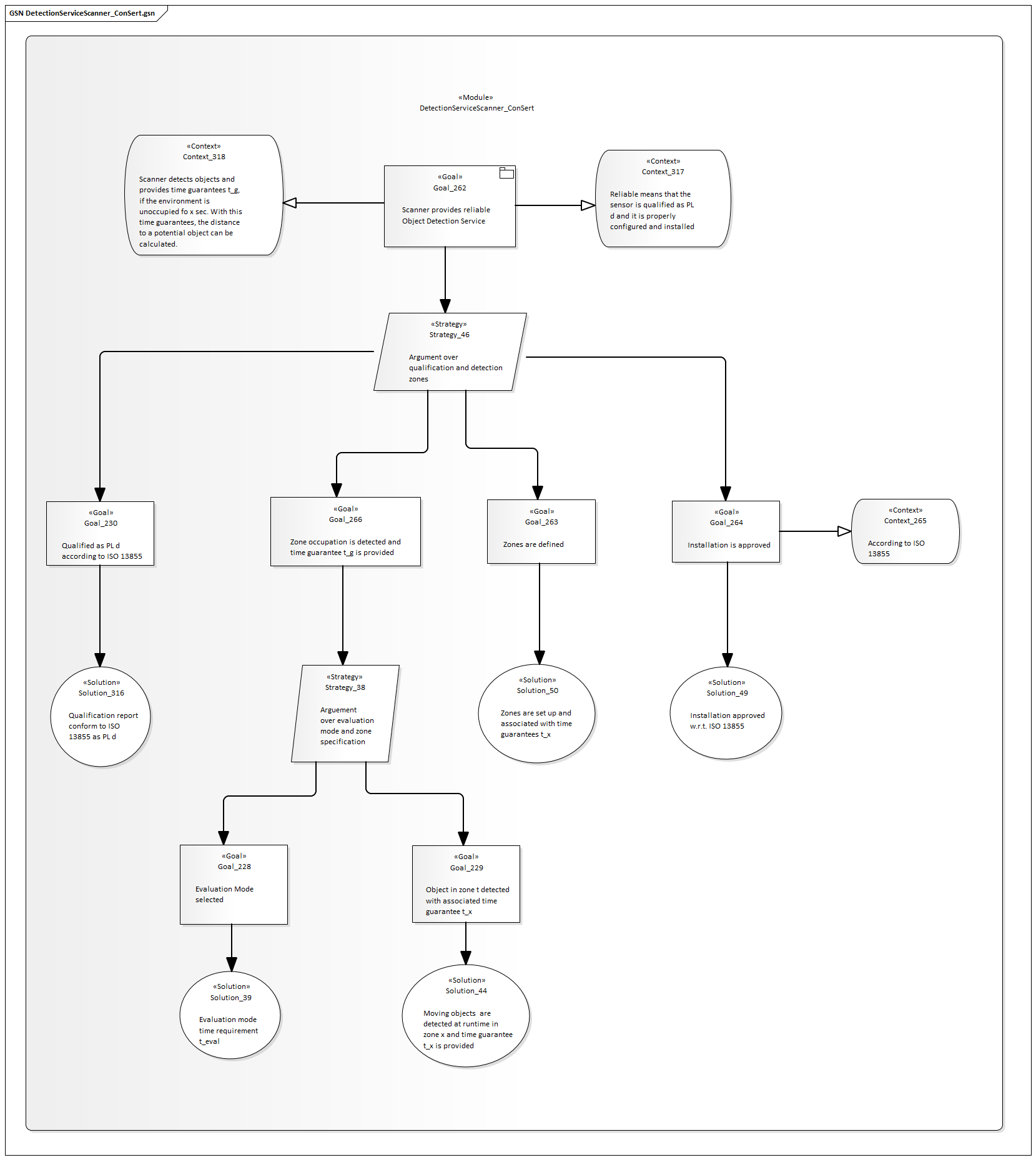
Scanner

Here, the provided time guarantee is impacted by various factors and in particular the operation mode of the sensor. For the laser scanner, the following considerations are made (in accordance with ISO13855):
\[t_{LS} = t_0 + \frac{TZ + Z_R + C}{1600mm/s} \]
- Response Time of the Sensor: \(t_0 = (t_s + t_i) \cdot n + t_p\)
- \(t_s\): Scan Cycle Time (often configurable, e.g. 30ms or 40ms).
- \(t_i\): Interference Protection Time (0 to 3ms).
- \(n\): Multi-evaluation (e.g. between 2 and 16).
- \(t_p\): Signal processing time given by data sheet (e.g. 35ms).
- \(TZ\): Sensor Tolerance (static value given in handbook)
- \(Z_R\): Reflection surcharges (static values given in handbook)
- \(C\): Surcharges for undetected reaching modes, depending on the installation height: \(C = 1200mm - (0.4 \cdot H_D)\)
Using this \(t_{LS}\) and an equivalent \(S_{LS}\):
\[S_{LS} = 1600 mm/s \cdot t_0 + TZ + Z_R + C\]
Note that this is the minimal case, i.e. if the zone has a size of \(S_{LS}\) we can not guarantee more than 0 sec to other systems (all time budget is used for the scanner itself). If we set the zone to a larger value \(S\), we get \(S_{diff}\) and respectively \(t_{diff} = \frac{S_{diff}}{1600 mm/s}\) as a time budget. The matching guarantee (for this zone and scanner config) then guarantees \(0\ \mathrm{..}\ t_{diff}\).
Note that different safety zones (with increasing size) can guarantee larger values of \(t\). Also the configuration options (e.g. multi-mode evaluation) have an impact.
Runtime ConSerts
Finally, using conserts-rs, we have generated various runtime artifacts:
- A ConSerts Submodel
- A ConSerts Runtime Monitor, supporting the intended target runtime:
- Rust applications, without additional modifications
- Bare-metal applications using
#![no_std] - ROS nodes using
rosrust - Other applications using the foreign function interface
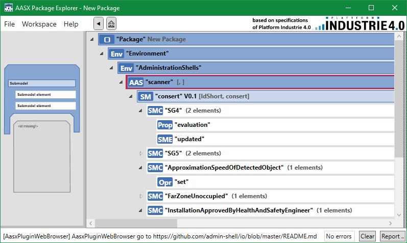
ConSerts Submodel
The following shows the automatically generated, Industry-4.0 compatible, submodel that describes the safety of our laser scanner system.
ConSerts Monitor
#![allow(unused)]
fn main() {
// properties.rs
#[doc = "Approximation Speed of Detected Object X m/s"]
#[derive(Clone, Copy, Debug, PartialEq)]
pub enum ApproximationSpeedOfDetectedObject {
    Unknown,
    Known(uom::si::f64::Velocity),
}
}
#![allow(unused)]
fn main() {
// evidence.rs
impl RuntimeEvidence {
    pub fn from(runtime_properties: &RuntimeProperties) -> RuntimeEvidence {
        // ...
        let rt_e4 = {
            use crate::properties::ApproximationSpeedOfDetectedObject::*;
            match &runtime_properties.approximation_speed_of_detected_object {
                Unknown => false,
                Known(value) => {
                    (0f64..=1f64).contains(&value.get::<uom::si::velocity::meter_per_second>())
                }
            }
        };
        // ...
    }
}
}
#![allow(unused)]
fn main() {
// guarantees.rs
#[doc = "Far Environment Unoccupied by Humans"]
pub struct Sg5;
impl Sg5 {
    pub fn evaluate(runtime_evidence: &RuntimeEvidence) -> bool {
        {
            let c0 = {
                #[doc = "Far Zone Unoccupied."]
                let c0 = runtime_evidence.rt_e6;
                #[doc = "Approximation Speed of Detected Object <= 2m/s"]
                let c1 = runtime_evidence.rt_e7;
                c0 || c1
            };
            #[doc = "Installation Approved by Health and Safety Engineer"]
            let c1 = runtime_evidence.rt_e5;
            c0 && c1
        }
    }
}
}
ROS Application Leveraging the Monitor
Note: This is an exemplary deployment using the Robot Operating System (ROS) version 1. ROS1 cannot be used in safety-critical domains, however the approach for developing an application is going to be similar.
The following shows how we can run a ROS monitor in a separate thread and manipulate the runtime properties in the main thread.
Due to monitor.rtp being an Arc<AtomicCell<RuntimeProperties>>, thread-safe access is possible.
Notice that AtomicCell uses compare-and-swap.
In our example, we ignore if this operations fails due to concurrent access.
A different solution would be to implement a bounded number of retry attempts to provide the information.
use consert_edcc2021::ros::RosMonitor;
use uom::si::f64::*;
use uom::si::frequency::hertz;
use uom::si::velocity::meter_per_second;

fn main() {
    let freq = Frequency::new::<hertz>(10);
    let mut monitor = RosMonitor::new();
    let mut rtp = monitor.rtp.clone();
    thread::spawn(move || monitor.run_standalone(freq));

    loop {
        // TODO: use actual sensor reading instead of constant
        let sample = Velocity::new::<meter_per_second>(5.0);

        let r_old = rtp.load();
        let mut r_new = r_old.clone();
        r_new.approximation_speed_of_detected_object =
            ApproximationSpeedOfDetectedObject::Known(sample);
        rtp.compare_and_swap(r_old, r_new);
        thread::sleep(Duration::from_millis(100));
    }
}
conserts-rs
conserts-rs is a library and set of command-line tools for working with ConSert models.
The goal of this library is to allow both safety engineers as well as (embedded) software developers to work with ConSert models. These models come in the form of files, generated e.g. via the safeTbox software. Usage of these models includes both runtime safety evaluation of single systems (where conserts-rs helps in auto-generating code) as well as the safety evaluation of the collaboration of several systems (where conserts-rs checks the composability).
Functionality
conserts-rs supports the following workflows:
- Parsing (and validating) these models.
- Compiling Rust crates that contain logic for evaluating ConSerts at runtime. This crate is:
- Usable for either
- embedded targets that require
#![no_std], - ROS (Robot Operating System), as it brings ready to use ROS nodes along, or
- any other system in which a binary generated from Rust can be deployed.
- embedded targets that require
- Unit-safe (with the help of uom).
- Usable through C/C++ bindings (with the help of cbindgen).
- Automatically documented, by making connections from the ConSert model to the generated code.
- Usable for either
- Validating the composition of several ConSert models.
- Visualizing the structure and current evaluation state of ConSert models.
Terms
The following introduces terms that are used in the context of ConSerts:
-
Dimension: A dimension is used to specify an aspect of a guarantee or demand.
-
Inter-Device Evidence:
-
Structured Assurance Case Metamodel (SACM)
-
{Composition, Compile, Design, Development, Evaluation Run}-Time
Science Behind
Peer-reviewed Publications
- "Plug-and-Produce... safely! End-to-End Model-Based Safety Assurance for Reconfigurable Industry 4.0" - Daniel Hillen, Tom Huck, Nishanth Laxman, Christoph Ledermann, Jan Reich, Patrick Schlosser, Andreas Schmidt, Daniel Schneider, Denis Uecker - 8th International Symposium on Model-Based Safety Assessment, Munich, September 2022
- "Live in ConSerts: Model-Driven Runtime Safety Assurance on Microcontrollers, Edge, and Cloud" - Andreas Schmidt, Jan Reich, Ioannis Sorokos - 17th European Dependable Computing Conference, Munich, September 2021
- "Engineering of Runtime Safety Monitors for Cyber-Physical Systems with Digital Dependability Identities" - Jan Reich, Daniel Schneider, Ioannis Sorokos, Yiannis Papadopoulos, Tim Kelly, Ran Wei, Eric Armengaud, Cem Kaypmaz - 39th International Conference on Computer Safety, Reliability, and Security, Lisbon, September 2020
- "A Runtime Safety Analysis Concept for Open Adaptive Systems" - S. Kabir, I. Sorokos, K. Aslansefat, Y. Papadopoulos, Y. Gheraibia, J. Reich, M. Saimler, R. Wei - 6th International Symposium on Model-Based Safety and Assessment, 2019.
- "Conditional Safety Certification of Open Adaptive Systems" - Daniel Schneider, Mario Trapp - ACM Transactions on Autonomous and Adaptive Systems, vol. 8, no. 2, pp. 1-20, 2013
- "Engineering Conditional Safety Certificates for Open Adaptive Systems" - Daniel Schneider and Mario Trapp - IFAC Proceedings, 2013
- "A Safety Engineering Framework for Open Adaptive Systems" - Daniel Schneider and Mario Trapp - 5th IEEE International Conference on Self-Adaptive and Self-Organizing Systems (SASO), 2011
Theses
- "Assuring Functional Safety in Open Systems of Systems" - Mario Trapp, Habilitation, 2016
- "Systematic engineering of safe open adaptive systems shown for truck platooning" - Jan Reich, Master Thesis, 2016
- "Conditional Safety Certification for Open Adaptive Systems" - Daniel Schneider, Dissertation, 2014
Legal
Citing
If you want to refer to this project, use the following
@misc{conserts,
      author = {{Fraunhofer Institute for Experimental Software Engineering (IESE)}},
      title = {{Opus: The Book of ConSerts}},
      howpublished={Web page},
      url = {https://conserts.tech},
      year = {2022}
}
License
Opus - Book of ConSerts (this project) is distributed under the following licenses:
- The code samples contained within this project are licensed under the terms of both the MIT License and the Apache License v2.0.
- The written prose contained within this project is licensed under the terms of the Creative Commons CC-BY-SA v4.0 license.
Copies of the licenses used by this project may also be found here:
Contributors
- Andreas Schmidt
- Daniel Hillen
- Nishanth Laxman
- Jan Reich
- Ioannis Sorokos
- Denis Uecker
![]()
- Christoph Ledermann
- Tom Huck
- Patrick Schlosser
Funding
![]()
The German Federal Ministry for Economic Affairs and Climate Action (BMWK) supported this work within the research project "FabOS: the open, distributed, real-time capable and secure operating system for production" under grant 01MK20010A.